Saturday, June 9, 2018

Installing the keel

Finally, I've reached the point of installing the keel on my Glen-L Zip.

Let's pick up where we left off: the transom knee needed a 7-7/8" tapered shim.


I made the shim, trimmed it to length, and epoxied it to the transom knee. After I sanded away the epoxy mess, it looked like this...


Trimmed & drilled

A little more primer...


Countersink the holes for the carriage bolts, so that the washers can land on a flat surface...


So, when I trimmed the shim, that obviously left a bit of a leftover piece. Keep that in mind. It comes into play later.

Now let's get to the keel installation. First, the prep work:

I'm embarrassed to admit that I had to Google how to properly install a carriage bolt in wood. But, one of the tenets of this blog is that I will openly share both my mistakes, and what I've learned, in an effort to help others. Surely I'm not the only person in the world who didn't know how to use a carriage bolt!

For those who don't know... the whole point of a carriage bolt is that you don't have to hold it with a wrench at one side while you tighten the nut at the other side. That's what the square part at the top is for. Drill a hole the same diameter as the bolt. Then, countersink the hole with a drill bit that is the same diameter as the width of the square part. Make sure you don't oversize this countersunk part. The square will drop right in, and grab hold when you tighten the nut. Pure genius.


Carriage bolt & countersunk hole at the keel-to-stem joint.
Marks on the keel, showing where to put the epoxy. This is the keel-to-transom joint.

Marks on the keel, showing where to put the epoxy. This is the keel-to-Frame #4 joint.

Marks on the keel, showing where to put the epoxy. This is the keel-to-stem joint.

I took someone's wise advise to cover all that finishing work I've done on the dash so far.

Safeguarding against gluing the frame to the construction form. Trust me... I learned from the Utility that it doesn't take much epoxy to cause you a real problem. If you use blue tape like this, be sure to remove it before the epoxy cures. Otherwise, it'll leave you one unholy mess to clean up.

Making sure Frame #2 is vertically level.
Okay. Remember the leftover piece from the transom knee shim? This is where it comes into play. 

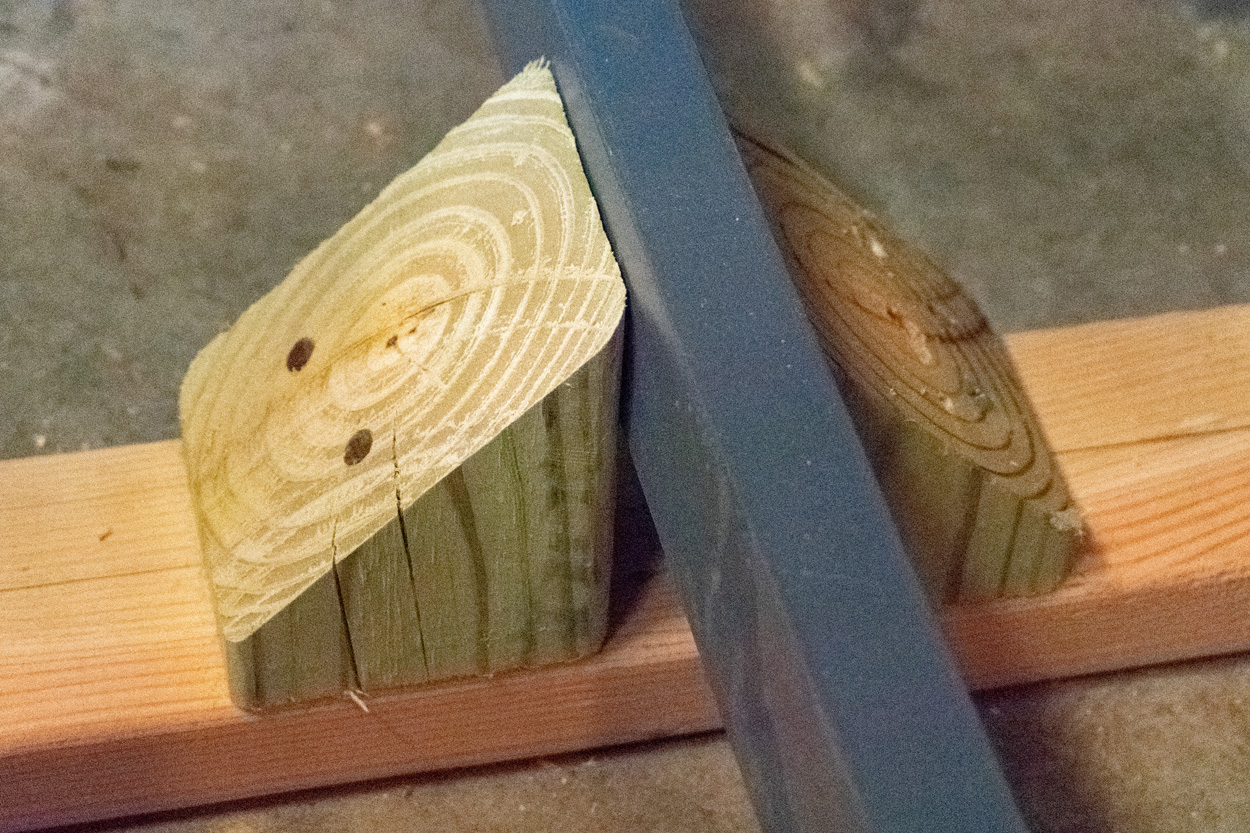
I had tapered the very front of the keel, where it butts against the stem. I thought, "how could I possibly mess up a simple 45° cut with a mitre saw?" Well, I did. I wish I had waited & cut this after the keel was installed. In any case, the leftover piece of shim was perfect to make... well... another shim. I just cut it at 45° with my mitre saw, then marked out & cut a "baby shim" for the front of the keel.


Oops. Well, not the end of the world.

"And shim begat baby shim." —Michael 6-9: 18

Now then, time to attach the keel with thickened epoxy:


I clamped my 4-foot level to the keel to keep the aft flat.

Front of the keel, clamped and bolted into place. Here, I've got the shim epoxied and clamped into position on one side. I'll do the other side later.

This is how I clamped the keel firmly into the transom notch. The cross-board is not attached to anything, so it won't get in the way of attaching the transom knee later.

I carefully scraped away the epoxy squeeze-out... especially at the keel-to-transom joint. This is where the knee must fit, as precisely as possible.


Peace, brothers and sisters.

Friday, June 1, 2018

Drilling the keel and transom knee

Soon, it will be time to attach the keel to the frames. 

That will involve bolting the keel to the stem, bolting the transom knee to the transom, and finally — bolting the keel to the transom knee.

This week I ordered the bronze carriage bolts from Glen-L, as well as some more epoxy since I'm almost out. Glen-L is currently in the middle of the company's first-ever move from their original 1953 building into a new facility in San Clemente, CA. That's a pretty big undertaking, so it's understandable if there turns out to be a little delay.

Meanwhile, I've started drilling the holes for those carriage bolts. It sounds simpler than it really is.

Let's take a look at the transom knee first.

In order to drill the holes as straight as possible, and on the centerline, I decided to use my drill press instead of a hand drill. This will also keep the holes at a 90° angle to the knee's flat contact surfaces.


Here's the complication. My drill press has a two-inch travel, which is not enough to go all the way through the knee. Not impossible, but I had to get creative to make this work. 

First, I started with a small drill bit for the pilot hole. In order to keep the hole as clean as possible, I used progressively larger-diameter drill bits to enlarge the hole toward my goal of 1/4". None of these initial drill bits went all the way through.

Finally, it was time to run a 3/16" bit all the way through the knee. The problem was, how? The bit itself was long enough, but the two-inch travel wasn't. 

I drilled the 3/16 as far as it would go. Then, I loosened the chuck and pushed the bit as far upward as I could and tightened it in place temporarily.

Then, I raised the table of the drill press as high as I could & still get the knee under the drill bit. With the knee in place, I loosened the chuck, and pushed the drill bit downward into the hole. I re-tightened the chuck, held the knee firmly in place, and turned the drill press on. 

Thankfully, it didn't bind and spin the knee right out of my hand.


With the drill press running, I finished drilling the hole all the way through the knee. Of course, I had to do all this in reverse in order to move the knee for the next hole. Then, I had to repeat the whole process for the other 3 holes. 

Then, all over again with the 1/4" bit. 


Time-consuming, but it worked. At one point, the drill bit ran into one of the bronze screws holding the knee together. I was concerned that might happen. Fortunately, the drill bit cut right through the softer bronze, and little shavings came flying out of the hole along with the sawdust.


Now, for the other end of the keel.

I started by drawing the centerline on the keel, and lining it up with the centerline of the stem. Then I clamped the entire keel into place, end-to-end.

Since the stem is now permanently attached to Frame 5-1/2, I had no choice but to use a hand drill. The challenge was finding a way to drill straight downward through the centerline so that the hole was centered and straight.


To help with this, I took a block of scrap wood that was roughly square, and close to the same width as the keel. I marked the centerline on this piece, then drilled a pilot hole through it with my drill press. This would be my drilling template.

I aligned the centerline of the template on the centerline of the keel, and clamped it firmly into position. Then, I drilled downward through the template, through the keel, and into the stem.


After I drilled two pilot holes using the template, I removed it. The full length of the keel was still clamped firmly into place.

As I did with the transom knee, I used increasingly larger drill bits in the hand drill until I had 1/4" holes all the way through. The resulting holes weren't perfectly on the centerline on the other side of the stem, but they were close.

The next step was to fit the transom knee.

I clamped it into place, firmly pressed against the keel and the transom.


The fitting was really good against the keel, as well as the bottom frame member of the transom. However...


The fitting against the motor board wasn't so good. Apparently, the motor board is thinner at the top than it is at the bottom, leaving a wedge-shaped gap.


Time, once again, to make another shim.

After a lot of careful sanding on a scrap strip of mahogany, I had a thin and long wedge-shaped shim.


After some meticulous fitting, re-fitting, and more sanding, it fit into the gap nicely. 


The next step will be to trim the shim and epoxy it to the knee.

Sunday, May 27, 2018

Stem attached.

The photos say it all.

I made this blocking out of leftover 2" thick mahogany.

Dry-fitting the stem blocks.

Dash inlay sanded for encapsulation coat #2.

Areas marked off for sanding on stem & Frame # 5-1/2.

Quick, if ugly, sanding on the frame for better epoxy adhesion.

Quick, if ugly, sanding on the stem.

Stem "glued and screwed" into place.

Detail shot of blocking.

Should be pretty sturdy.

A little encapsulation on the transom.


Saturday, May 26, 2018

A Tour of the Construction Form

Today is my mom's birthday. So, let me first start off by saying:

HAPPY BIRTHDAY, MOM!!!

I'm looking forward to celebrating her birthday a little later today with my parents and my kids. She's a picture-postcard of the "Baby Boomer" generation, my mom. My grandad came home from Europe to rural Georgia after the end of the second world war. About a year later, there was my mom.

For fans of classic boats, the following decade brought an economic boom in the U.S. that yielded some of the most beautiful boats ever put in the water. That boom also brought a high demand for kit boats and plans for boats that could be built at home. The Glen-L Zip that I'm building is a product of that era. Glen L. Witt published the design when my mom was about 8 years old.


Birthday Girl!
Speaking of the boat... It has finally become a three-dimensional project. All the frames are on the construction form, and I've begun fitting the keel. My construction form this time around isn't as heavily-built as my last one. It's mostly as-per-the-plans, with a couple of my own ideas added — and, naturally — a few mistakes that I had to fix. So, here's the tour:

Here is an overall view, with the frames all mounted on the form.


The legs were built from scraps of pressure-treated lumber left by the contractor who recently built my back deck. I left the tops open, so that it would be easier to work underneath the hull if necessary.


The longitudinal stringers on the form are made from 2x4s that I bought at Lowe's. To insure symmetry, I screwed the boards together before making the cuts for notches, etc. The plans actually call for 2x6 boards... a mistake I didn't catch until later. However, I believe these will be fine... not to mention lighter if they come off with the hull.

The supports for the stringers are attached from the inside-out, as are the stringers themselves. They are attached with hex-head lag screws. The idea is that, when the time comes to remove the hull, I should be able to get underneath (as before with the Utility) and detach the stringers from the legs. Hopefully, this will make it easier and lighter to remove the hull and flip it over.


I pre-built these T shaped spacers to hold the stringers exactly 18 inches apart. I attached them to the stringers when they were upside-down on my garage floor. The idea is that the floor would keep the upper (topside) edge of the stringers in lateral alignment.


The forward-most spacer is positioned to provide additional support to the notch for frame 5-1/2. That notch is cut 3 inches deep, at the very front of the stringer. Obviously, a 3-inch cut into a 3-1/2 inch "2 x 4" doesn't leave much to support the weight of the frame and hull. This is clearly why the plans called for 2 x 6 boards. The spacer is attached from the bottom with 2-1/2 inch wood screws. It should provide adequate support.

Notice the arrow on the forward legs. I had to remove this set of legs in order to slide Frame #4 onto the stringers. Thankfully, the hex head lag screws made this fairly easy. The arrow was to make sure I re-attached the legs exactly as they had come off.

The forward end of the stringers are cut and beveled to allow clearance for the planking that will bend around Frame 5-1/2 later on.


Frame #5-1/2 is attached to the forward spacer with 2-1/2 inch wood screws to prevent movement of the frame. This also holds it in position where it is horizontally level. I added blocking to the breasthook support to hold Frame 5-1/2 level vertically.


Blocking to support the breasthook so that it is exactly 21 inches from the topside surface of the breasthook to the top of the stringers.


The stem support board is attached to the forward legs via three 90° brackets.


The plans call for the stem support board to be 14 feet long — long enough that it can be attached to all 3 sets of legs. This is to hold it firmly in position, centered exactly on the centerline. I don't know what I was thinking when I bought an 8-foot board. Not surprisingly, I found the board could easily be kicked out of alignment. Totally unacceptable.

To remedy this problem, I attached a leftover 2x8 to the back 2 sets of legs. The forward end of this board overlapped the back end of the stem support by about 6 inches. I attached the two at this joint with the biggest gusset I could make out of scrap 1/4 inch plywood and a lot of wood screws. A little unconventional, but it works.


In addition to the original T shaped spacers, I added two more as blocking to support Frames 2 and 4. I further added 1 x 1 inch strips to these spacers, and the frames are attached to these with 2-1/2 inch wood screws. While this will work for the time being, it also creates something of a problem. The 1x1 strips are high enough that they will interfere with placement of the floor battens later on. So, these will need to be removed before I add the floor battens.


I added more 1 x 1 blocking to the sides of the stringers, to hold Frame #4 in position where it is vertically level.


I left the aft ends of the stringers at an overhang, to allow plenty of room to work on both sides of the transom.


The transom is screwed directly to the ends of the stringers, holding it in position at a 12° angle. I hated drilling holes through the transom. One 2-1/2 inch wood screw per side is all it took.


And, finally... fitting the keel into its transom notch.