The reason for that is fairly simple. The Glen-L plans show the transom drawn to its minimum, aft-most dimension. Not only is the transom mounted at a 12 degree rake, the sides of the boat also flare outward 10 degrees from the transom. So, the front of the transom is actually larger than the back.
But wait, there's more!
These beveled angles also mean that the notches for the keel, battens, chines and sheers should be cut at the correct angles for the best possible fit & strongest possible joint. It seems to me that the easiest & most accurate way to make those cuts would be to cut them from the back (as they are drawn on the plans) forward. Thus the need for accurately measured & drawn frame lines on the back of the transom.
SO, with the back of my transom marked, I was ready to attach the frame parts.
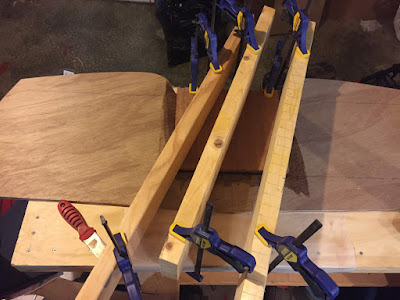
First, I did the motor board. I used epoxy, thickened with mahogany wood dust, to simply glue it into place. I did not use screws or nails. Clamping it into position accurately was a bit of a challenge, but I got it. Learning from past experience, I meticulously scraped away the epoxy squeeze-out. If left to cure in corners, etc, dried epoxy will create a fitting nightmare.
 |
| Attaching the motor board, using multiple clamped 2x4s to press the motor board firmly into place. |
 |
| Attaching the floor beam and frame sides. |
 |
| Transom frame sides, marked for Starboard and Port |
 |
| Beginning to trim the edges on my Zip transom. |
For now, the next step is to trim the edges, and cut the notches for the keel, chine and sheer.
No comments:
Post a Comment