So, for now, I bring you The Tedious Tale of Zip Frame #2.
Frame #2 is located in-between the transom and Frame #4. It essentially forms the front end of the rear cockpit. The deck beam of Frame #2 forms the back of the bridge deck.
 |
| Glen-L Zip with a classic 50hp Merc. The "dashboard" at the front of the rear cockpit is the deck beam of Frame #2. |
When I was drawing out the side, or "rib," pieces of Frame #2, I was happy to find that the remnant of my mahogany board was also long enough for the floor beam.
 |
| The side "ribs" of the frame turned out fine. |
I decided to try something new.
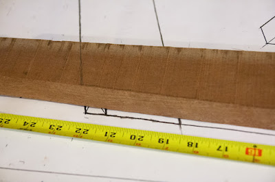
Normally, I just trace the patterns onto the wood. This time, I thought I'd try my hand at lofting the floor beam. All the lines looked straight, so I thought it should be relatively easy and simple.
So, I marked the centerline on my board, and measured the lines on the plans. I marked the reference points on the wood, and drew the full-length lines. To get the deadrise "V" at the bottom of the frame, I carefully measured the angle on the plans with my angle finder. Then, I similarly transferred the angled line onto my board. Everything seemed to go off without a hitch.
 |
| The underside of the floor beam is undercut as a result of my misjudgment of the angle. |
Then I checked the cut pieces against the plans. The side "ribs" (which I traced) are fine. However, the bottom of the floor beam shows an obvious misjudgment of the deadrise angle. No worries. I'll just laminate a couple of strips onto the bottom and re-shape it, just like I did on Frame #4.
I'm getting pretty good at that.
 |
| The strips will need to cover the outermost 22 inches on each side of the frame. |
No comments:
Post a Comment