Sunday, July 23, 2017

The Slow Saga of Zip Frame #4 — part seven

Finally, I bought a new 14' board of 4/4 African Mahogany to make the deck beams for frames 2 and 4. I cut the beam for frame 2 first, since it's less of a focal point than frame 4 (aka: the dashboard).

I wanted to take my time and make sure I got the dash right.

To start with, I simply traced the crown of the beam from the plans onto the remaining 7' rough-cut mahogany. The shape, as drawn on the full-size plans, would be too narrow to accommodate what I have planned for the dash layout.

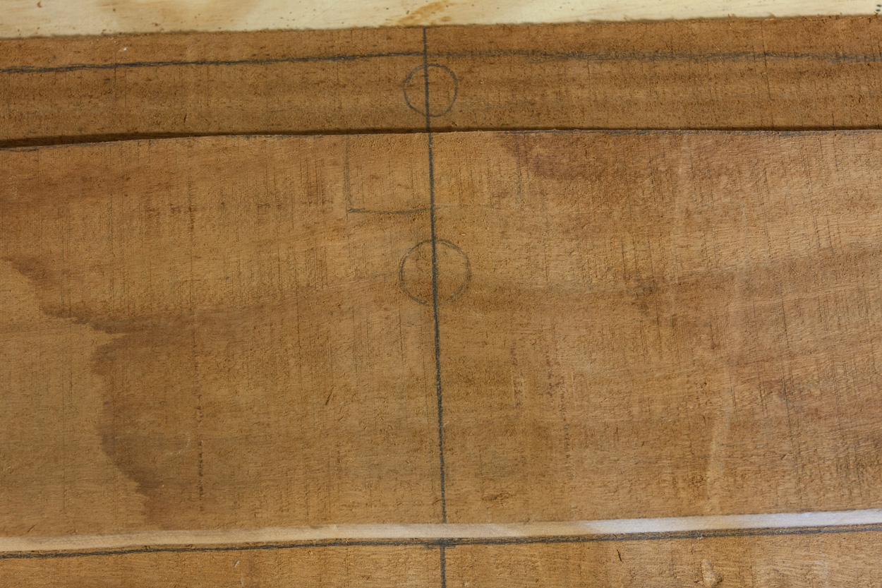
On the centerline, I marked the span at 6" and 6-1/4". The dash beam needs to be tall enough to accommodate a 5 x 10" oval in the center, for the instrument panel. It also needs to be tall enough to accommodate the 5" diameter bezel for the steering wheel, at the point halfway between the centerline and the sheer.


Marking the 6" and 6-1/4" span on the centerline.
For the shape of the dash, I decided to simply trace the lower line from the deck beam of frame #2. I aligned the frame 2 deck beam onto the centerline drawn for the dash, with the bottom aligned with the 6" mark.


Aligning the #2 deck beam on the centerline for the dash.
Then I traced the lower line. However, when I measured the beam height at the location for the steering wheel bezel, it was too short. So, I moved the beam down to the 6-1/4" mark, and traced the line again.


Tracing the lower shape of the frame 2 deck beam.
This time, there was an adequate span for the steering wheel bezel.


Measuring the span for the steering wheel bezel.
Below is the layout that I have planned for the dash. I want a basic, minimalist instrument cluster mounted in an inlay at the center. The inlay will be a complimentary, contrasting wood... probably maple. The gauges will be a 4" tachometer in the middle, surrounded by a 2" depth gauge and 2" volt meter on the sides. Pull switches for the lights will be centered along the bottom, in-between the gauges. On the other side of the steering wheel will be a small panel switch for the bilge pump.

That's the plan for now, anyway.


The inspiration came from this inlaid dashboard on a Glen-L Malahini that I got to ride in at the 2012 Glen-L Boatbuilders Gathering. When I saw it, I knew that I wanted to do something similar.


What a view!

At the moment, my dash looks like this:


Saturday, July 22, 2017

The Tedious Tale of Zip Frame #2 — part five

It was a quiet Saturday morning in late July. My boy was asleep, enjoying the peace of his sister being away at a friend's house. It was, after all, one of the last weekends of summer, before starting a new year of school. 

The sunrise was slowly filling his room with a luminescent yellow glow. All was quiet and still.

It's a perfect set-up for the tranquility to be shattered by the sound of a lawnmower, or a neighbor's weed-eater, right?

Not exactly.

The tranquility was shattered when I started the saw. Its blade caught the dense grain of the heavy mahogany board, kicking the saw back and slamming the board down onto the slab of plywood it was clamped to. The plywood was clamped to a pair of sawhorses, several feet above the concrete floor. Concrete floor. Cinderblock walls...

The acoustics were perfect.

I pressed the saw back into the board with more determination, and the fight between me and the mahogany was on. The sound was like a booming symphony of drums at a rock concert... only less rhythmic. And for a sleeping teenage boy, far less pleasant.

What did I care? I had ear protection.

I was determined. After all, within this expensive chunk of wood lay the deck beam for frame #2, which hadn't been touched since February.


Sunday, July 16, 2017

Grey Area

I almost titled this post "Fifty Coats of Grey," due to all the sanding and re-coating I've been doing. But, I decided not to. Maybe next time.

Work continues, slowly, on the Zip. I have been applying Aquagard 190 primer to the transom knee and frame #5-1/2.


Frame #5-1/2 with notches cut, poster board template, and my modified 2"-wide transom knee.

When I originally constructed frame #5-1/2, I had intentionally left the notches for the sheer and chines uncut. Some builders prefer to only notch the frames once they are all mounted on the construction form, and the longitudinals are sprung.

I decided that those people are better woodworkers than I am. I also decided that, since the Zip has been a popular boat to build ever since it was introduced 63 years ago, in 1954, that the notch locations shown on the plans are probably accurate enough. In all that time, there don't seem to be many well-documented complaints. Good enough for me.

I have already cut these notches in the other frames and the transom. To "retro-fit" them into frame 5-1/2, I drew a template from the plans onto a piece of poster board. Then I simply placed the template on the frame, marked, and cut.

The floor batten notches remain uncut on all frames, however. I still have not decided if I will use 3 per side, or only 2.

Tucked away on one of the plan sheets is this statement where Glen mentions the option of using 3 floor battens on each side of the keel.

Monday, July 3, 2017

Revisiting the stem

Work has slowed considerably on the Zip. There are a couple of reasons for that:

The first and best reason is that I finally have a completed boat to play with. Now that the weather is warmer, I'd simply rather spend my time out on the lake in the Utility than cooped up in the garage working on the Zip.

The other reason basically comes down to planning. Every little piece and component is interconnected on a boat. For example, the shape of the dash beam depends on the layout of the gauges and switches. The layout depends on what gauges and switches I want to use.

Then, comes the question of a motor. 

If I get a 40 or 50 horsepower motor for this boat, my budget will basically demand a used 2-stroke motor. Here's the problem with that: I'd prefer not to use an old 2-stroke motor. Call it my inner tree-hugger. I'd rather have a cleaner-operating Evinrude E-TEC or a 4-stroke motor. And, you guessed it... those are just too expensive.

If I get a new motor, then my budget basically limits me to 20 or 25 hp. So, it's a matter of compromising either emissions, or power. For a lot of people, that's a no-brainer. Prioritize power. I get that. I do. 

However, power and speed isn't all that important to me. On the other hand, I don't want to invest all this time and work to wind up with an under-performing boat, either. So, if I opt for a 20–25hp motor, that decision will affect the length of the boat. The shorter "version" of the Glen-L Zip is called the "Flying Saucer." It's designed at 12' 3" and has a maximum horsepower rating of 25. 

And so there you have it: progress has been stalled by having to make decisions (and/or purchases) regarding instrumentation and power. What to do in the meantime?

Why not work on the stem?

If you read much about either the Zip or the Flying Saucer, you'll find a lot of comments about the boats' tendency to be light in the bow. Most builders look for ways to shift some weight forward, in order to keep the bow down. A popular choice is to mount the fuel tank up front, and I'll probably do that.

But, I decided to also add some bulk to the stem. 

As-designed, the stem is 1-1/2" wide (2 laminations of 3/4" plywood). I added additional 1/4" pieces to the sides, increasing the width to 2 inches (which is also what I did with the transom knee). I had to leave a 1-1/2" channel for frame 5-1/2 to fit into, because I did not want to widen the notch in the frame.


Here, you can see the 2 additional layers of 1/4" plywood attached to sides of the stem, forward of frame #5-1/2.
This photo shows how frame #5-1/2 fits onto the stem.

Here, I have clamped a scrap piece of 1/4" plywood onto the side of the stem, aft of frame #5-1/2. This allowed me to simply trace the shape of the stem onto the new parts, making sure to leave enough of a "channel" for frame #5-1/2 to fit into, without widening its' notch (and weakening the frame unnecessarily).


As I worked on the stem, I noticed that the breasthook was not accurately perpendicular to the stem. So, I also added a tapered piece to the top of the breasthook to correct it. This should help when the frames are all on the building form, and it's time to mount the stem into place.


Something just didn't seem right about the breasthook. So, I put the whole assembly in my vice and made sure it was level laterally.

Then, I made sure the breasthook was level, linearly.

The moment of truth. Checking the breasthook laterally, it was clearly nowhere close to perpendicular to the stem.

I found that the breasthook "dropped" almost 5/8" from tip-to-tip.
To resolve the issue, I made a shim by laminating 3 pieces of 1/4" plywood together: One full-width piece, one half-width piece, and one quarter-width piece. I faired it with a belt sander and a finish sander.


The shim worked within reason, so I epoxied it into place.