As you may have noticed from the photos up to this point, I did not pre-cut notches for the floor battens into the frames. That's because I planned to use the optional arrangement of 3 battens per side, rather than the standard 2 battens as drawn on the plans.
I wanted to wait until I could actually lay the battens on the frames, and place them as I wanted. What I've decided to do is to use 2-1/8" battens spaced 7 inches centerline-to-centerline from the keel, then 6 inches centerline-to-centerline from one another.
Here's how I went about cutting the notches for the floor battens:
 |
| The inner battens are on 7" centers from the keel. |
 |
| The floor battens are on 6-inch centers from one another. |
The battens, (or at least the two I have at the moment), are about the same thickness as my ruler. So, I will use the ruler as a guide to mark some reference lines.
At the aft end, I make sure to hold the ruler even with the underside of the batten, not flush against the 12° rake of the transom.
Using the underside of the ruler as a guide, I draw a line with a pencil to show how deeply to cut the notch.
Then, I clamped the batten into place and made some initial cuts, using the sides of the batten as a guide.
I used a block of wood with a 12° rake as a guide, so that the horizontal cut would be level, not angled like the transom. This block of wood is actually the former tail-end of the keel.
Here, you can see that I goofed one of the vertical cuts. Fortunately, it didn't get very deep before I noticed my mistake. I'll fill this in later, but hopefully most of it will get faired away when I get to that phase.
Using this block as a guide, I held the multi-tool blade against it as I made the horizontal cut.
 |
| Here's the cut through the transom. |
 |
| And the fitting of the batten into the notch. Not bad. |
That completes the notch cut into the transom. Now let's move forward to Frame #2.
As before, I used my ruler as a guide to mark the depth of the cut, since it's about the same thickness as the batten. The ruler is aligned with the edge of the frame, so that the mark for the cut will be at the same angle. (Remember that the boat is upside-down on the form, so what's showing is actually the bottom edge of the frame.)
 |
| Ruler aligned with the bottom edge of Frame #2. |
 |
| I'll mark the line with the scribe that is built-in to my sliding square. |
 |
| Line marked for the horizontal cut. |
 |
| Cutting guide and batten clamped into position. |
 |
| The vertical cuts were made by aligning the side of the multi tool's cutting blade with the side of the batten. |
 |
| The horizontal cut was made by aligning the bottom of the multi tool's cutting blade with the top of the cutting guide. I made minuscule finishing cuts with a coping saw. |
 |
| The batten drops right into place. |
Now, to repeat for Frame #4.
 |
| Cutting guides clamped into position. |
 |
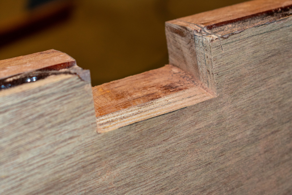
| Notch is cut. |
 |
| That line next to the notch isn't a cut. It's the end of a shim I laminated onto the frame earlier. |
 |
| Batten drops right in. |
Now, for the Limbers. These are openings in the frame, alongside the floor battens, to allow any water in the bilge to flow to the back of the boat for removal.
 |
| I used this roll of Duck Tape as a guide to scribe the curved line. Seriously... it's called "Duck Tape." |
 |
| Curved line scribed onto the frame. |
 |
| Making the rough cut with a coping saw. |
 |
| The rough cut is easily finished out with a Dremel tool fitted with a sanding drum. |
 |
| et Voilà |
 |
| Working backward, repeat for Frame #2. |
So there you have it. That's the procedure, or at least my version of it. Four more floor battens to go... but for the moment, I'm out of mahogany.