Saturday, December 31, 2016

New Year's Eve.

The clock is ticking away the final hours of 2016. I, for one, will be happy to bid this year farewell, and begin anew in the morning. Here's to 2017.

In the meantime, what is an amateur boatbuilder to do on New Year's Eve? Why not drill holes in a perfectly good transom?


Hey...why NOT drill holes in a perfectly good transom? That sounds like a GREAT idea!

Okay, okay.... there's a little more to it than that.

Back in July, I had begun to consider bolting the boat motor to Perseverance's transom. The strain on my back from mounting and dismounting the motor on every trip to the lake was becoming a bit much. However, I hesitated, due to some questions that arose regarding weight distribution and the towing dynamics of my trailer. Simply put, I needed input from someone with more experience.

At the G10 Boatbuilders Gathering in September, I got exactly that. A fellow builder who I know and trust took a closer look at the whole setup with me. We decided that the axle on my trailer is far enough aft that adding a little more weight to the back of the boat doesn't significantly affect the tongue weight. It helps that I have a small 8hp motor.

Essentially, we unhitched the trailer with the motor still on the boat. Even with the front wheel jack extended a little higher than "towing" height, the trailer did not tilt back, at all.

So, today I decided to mark the end of 2016 by drilling holes through the transom so that I can bolt the motor to the boat.

I started off slowly, with a small diameter pilot hole. Due to the proximity of the motor's mounting brackets, I was unable to use regular-length drill bits. Fortunately, I had a few longer ones left from drilling the hole for the bow eye.

First drill bit for the pilot hole

Initial pilot hole
And, we're through!
Now, for a larger drill bit...
...and a larger diameter hole...

...all the way through the transom.
Now, for the 5/16" drill bit.
So far, so good.

Pilot hole on the port side.
And then, a larger hole.

All done.
After the holes were drilled, I removed the motor. I will need to seal the inner diameter of the holes with epoxy before reattaching the motor.

The transom has gotten pretty scuffed up after several trips to the lake... mounting and dismounting the motor, etc. I have debated on adding an outer motor board, just to absorb the wear and tear, and protect the transom. However, I don't think I will. The scuffs are really just cosmetic blemishes, and the motor covers most of them when it's attached.

Besides, the scuff marks give the little boat some added character.


Scuff marks on the back of the transom

There are also scuff marks on the top of the transom, where the paint and primer have both been worn away.

Motor board on the inner side of the transom
Just for fun, I also set out the miscellaneous parts for the Zip so I could get them all in one photo for the first time...


From front to back: Stem & Breasthook Assembly; Frame # 5-1/2; Frame # 4; Frame #2; Transom Knee, and Transom.


Alright, then. By my clock, we have six minutes left to go. Goodbye, 2016. Hello 2017.

Happy New Year!

Tuesday, December 27, 2016

The Tedious Tale of Zip Frame #2 — part two

After much sanding of the floor beam, I finally got one side of it mostly smooth.

Mostly.


I decided to wait until the strips are laminated onto the bottom before I finish sanding. After all, the strips themselves and the epoxy squeeze out will have to be sanded, anyway. What would be the point of sanding the floor beam down to perfection.... only to have to sand it even more once the strips are glued on?


Besides, there were other problems with the floor beam that needed to be addressed.


The point of the deadrise angle is not aligned with the centerline of the frame.

Namely, the deadrise point at the bottom of the frame was off-center, by at least a quarter inch. I wanted it to be as close as possible to the marked centerline on the frame. 

It only took 3 passes across my planer/jointer to get it pretty darn close.


Much better.
It isn't dead-on precise, but it's certainly close enough for what I'm doing. (The center point is going to be cut away for the keel notch, anyway.) My goal is for all the parts to be as symmetrical from the centerline as I can make them.

After I did that, I cut a narrow piece of mahogany that I will use to make the 2 strips for the bottom of the frame. Since I had the planer set-up, I went ahead and planed one side so it will line up well with the (mostly) smooth side of the floor beam.


But, before I cut the shim strips, I wanted to take a closer look at the angular misalignment at the bottom of the frame. So, I laid it out on my full-size construction drawing:


The point on the centerline matches up pretty well with the drawing.

However, at the port end of the frame, the gap at the bottom is pretty substantial.

By my measurements, the port side has a 3/8" gap at the end.

The length of the port gap is 23-1/2 inches.

The gap at the starboard end is 1/4".

The length of the starboard gap is 24 inches.
After taking some measurements, I decided on my plan. I'll cut the shim strips each 24 inches long. One will need to end at 3/8" thickness (or slightly more) for the port side. The other will need to end at 1/4" thickness for the starboard side.

Port end of Frame #2.

Starboard end of Frame #2.
I'll post another update once I make some more progress. 

Until then... keep on keepin' on.

"for in due season we will reap, if we do not give up."     
— Galatians 6:9 

Sunday, December 25, 2016

Merry Christmas

Well, it's Christmastime again. Merry Christmas to you.

The Tedious Tale of Zip Frame #2 continues. However, I haven't made enough visible progress to be worthy of a "part two" installment yet.

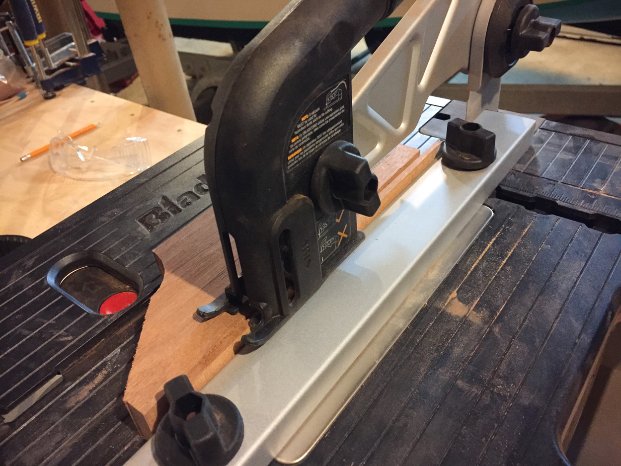
I have sanded the ribs smooth from the rough-cut lumber. The work has all been hand-sanding, and of course I continue to collect as much of the mahogany wood dust as possible.

I have also trimmed the ends of the floor beam, and begun hand-sanding that as well. 

Aside from that, I have sanded the outer coat of encapsulating epoxy on Frame #5-1/2 in preparation for painting.

That's all I've got for now. So, I'll leave you with a status update on the current state of Zip parts. (The last such update being in July). And, since MY Zip is far from being completed, I'll leave you with a couple of photos of someone else's.


Current Status of Zip Parts
PartStatus
Stem & Breasthook Assembly2 coats of epoxy
Frame 5-1/2Forward face has 3 layers of epoxy. Rear face has 2 layers. Entire frame has been sanded in preparation for painting
Frame 4Keel notch widened. Floor beam and ribs currently dry-fit with 1/4" plywood gussets. Deck beam / dashboard currently in design phase.
Frame 2Ribs cut, notched and sanded. Floor beam cut. Deadrise angle on floor beam is too sharp, and needs to be fixed.
Transom KneeCoated with 3 layers of epoxy
TransomInitial assembly complete: Frame and motor board epoxied to 1/2" plywood backing. Notches with 10° bevel cut for sheer and chines. Notch with 12° bevel cut for keel.


This is the very first Glen-L Zip I ever rode in. It was a beautifully-constructed boat. The craftsmanship was superb, all the way down to the stitches in the upholstery aligning with the deck seams. It remains the only Zip I've seen first-hand (so far) with a carpeted floor. I well remember my first impressions of the ride: that the boat is smaller in-person than it seems from photos... yet the interior space is more spacious than one would think from such a small boat. Fond memories.

For now, we'll just say that the "MC" on the side of the hull stands for "Merry Christmas."


Tuesday, December 13, 2016

The Tedious Tale of Zip Frame #2 — part one

The Slow Saga of Zip Frame #4 is far from over. However, that part of the project is temporarily on hold for planning and due to material limitations. 

So, for now, I bring you The Tedious Tale of Zip Frame #2.

Frame #2 is located in-between the transom and Frame #4. It essentially forms the front end of the rear cockpit. The deck beam of Frame #2 forms the back of the bridge deck.


Glen-L Zip with a classic 50hp Merc. The "dashboard" at the front of the rear cockpit is the deck beam of Frame #2.

When I was drawing out the side, or "rib," pieces of Frame #2, I was happy to find that the remnant of my mahogany board was also long enough for the floor beam.


The side "ribs" of the frame turned out fine.

I decided to try something new.

Normally, I just trace the patterns onto the wood. This time, I thought I'd try my hand at lofting the floor beam. All the lines looked straight, so I thought it should be relatively easy and simple. 

So, I marked the centerline on my board, and measured the lines on the plans. I marked the reference points on the wood, and drew the full-length lines. To get the deadrise "V" at the bottom of the frame, I carefully measured the angle on the plans with my angle finder. Then, I similarly transferred the angled line onto my board. Everything seemed to go off without a hitch.


The underside of the floor beam is undercut as a result of my misjudgment of the angle.

Then I checked the cut pieces against the plans. The side "ribs" (which I traced) are fine. However, the bottom of the floor beam shows an obvious misjudgment of the deadrise angle. No worries. I'll just laminate a couple of strips onto the bottom and re-shape it, just like I did on Frame #4.

I'm getting pretty good at that.


The strips will need to cover the outermost 22 inches on each side of the frame.

Tuesday, November 29, 2016

The Slow Saga of Zip Frame #4 — part three

The long holiday weekend proved to be fruitful in my cramped little boat shop. After a little sanding, I started drawing out some frame gussets. Next thing you know, I had 3/4 of the frame assembled.

Floor beam, after sanding the laminated strips to shape.

Floor beam and one of the side pieces.

Drawing out frame gussets on scrap pieces of plywood.

Next thing you know, the gussets were cut, sanded, and screwed onto the frame.

Starboard side detail.

Port side detail.

Thursday, November 24, 2016

The Slow Saga of Zip Frame #4 — part two

Happy Thanksgiving!

With the basic sanding done, and the keel notch widened, I next laid the floor beam on top of my full-size construction drawing in order to check the shape.


Floor beam on the construction drawing.
The good news is, that one side of the floor beam was a darn-near perfect match with the drawing from the plans. Unfortunately, however, the other side was not. It had been over-cut, and as a result was not wide (or tall) enough in the outer section of the curve.


Here you can see the gap between the actual floor beam, and the line where it should be.

So, I decided to remedy the situation by laminating on a thin strip of wood. Fortunately, I had a scrap piece of mahogany that was almost exactly the same width as the floor beam. I used my little Rockwell BladeRunner to cut a couple of strips approximately 3/16" thick.

Cutting a couple of thin strips of mahogany.

I clamped the strips into place to see how they fit. It was a relief to see that this was going to be an apparently easy thing to do.

Test-fitting the strips.


So, this morning, I removed the clamps and prepped my work area with a sheet of waxed paper.


I gathered all the items I'd need: Scale, mixing cup, scraper, chip brush, mixing stick, rag, epoxy, and of course... my bag of mahogany wood dust.


The rest was easy and straightforward. I mixed a small batch of epoxy & thickened it with wood dust. I brushed it onto both mating surfaces, clamped it all down, and scraped away as much squeeze-out as I could. In a few more hours, it should be nice and solid.

A little epoxy, and a lot of clamps. Now, just to wait for the epoxy to cure.

Thanks for reading... and good luck with Black Friday tomorrow.

"in everything give thanks; for this is the will of God in Christ Jesus for you."     
— Thessalonians 5:18 

Monday, November 21, 2016

The Slow Saga of Zip Frame #4 — part one

Frame #4 on the Glen-L Zip is the location of the boat's dash board (steering wheel, gauges, etc).


Glen-L Zip dashboard
The dashboard beam at Frame #4 is customizable to whatever shape or arrangement you please. This Glen-L Zip has the optional walk-through bridge deck. And, as you can see, a classic Mercury motor.

Progress on my Frame #4 has been moving at a snail's pace... but I am making progress. For most of the month, it has been daily (if brief) sessions of hand-sanding the frame components at 5:00 am with my morning coffee.

That would be three out of the four frame components. I actually ran out of enough length of the $94 mahogany board I bought back in May, so I have not yet cut the actual dashboard beam.

Glen-L Zip dashboard
Another example of a dashboard on a Glen-L Zip, and this builder's interpretation with the multi-colored overlay of woods.

Glen-L Zip dashboard
Here's yet another example of a dashboard on a Glen-L Zip. This photo also shows it more in context with the rest of Frame #4.
Floor beam for Frame #4. The side beams can be seen in the foreground.
Most of the work this month has been hand-sanding the rough-cut mahogany parts from this:

Rough-cut mahogany as I bought it at the lumber yard.
Into a smooth surface like this: 

Sanded mahogany side beams for Frame #4.
In the process of sanding, I have continued to save the mahogany wood dust for future use as a thickening agent for epoxy.


The paltry amount of wood dust I'd collected a month ago.

Now I have about 3X that amount, just from working on Frame #4 — so far.
After all the sanding, I found that I needed to widen the keel notch in order to accommodate the 4" keel. It's not perfectly symmetrical, but it's within acceptable tolerances for me.
So, there you have it for Frame #4 progress so far. It's slow progress, but then again I'm in no major hurry. Until I figure out where I'm gonna put the other boat, I don't have room to set up the Zip construction, anyway.

But, I'll get there.


"— being confident of this very thing, that He who has begun a good work in you will complete it"     
Phillipians 1:6