Friday, May 24, 2013

Reinforcing the construction form

During the fitting process for my sheer clamps, I noticed a little problem: the boat's breasthook would turn slightly toward the direction where I was applying pressure to dry-fit the sheer. I'd thought that simply having the chines in place would be sufficient to hold the breasthook onto the boat's centerline, but it was not. I also noticed that the stem itself would flex a little bit, despite the chines being fastened into place.

I decided that it would be a good idea to re-build and reinforce that part of my construction form that supports the breasthook. I've always felt that this area was the weakest point in my construction form anyway.

The first step was to completely remove this part of the form. This was relatively easy, as all I had to do was un-screw the base board from the forward support structure, and then just kick the whole assembly out from under the stem.

The next step was to remove the blocking assembly from the forward part of the base board. I kept the blocking assembly itself intact, as the height was correct. The plan was to simply replace it onto the new base board.

For the new base board, I'd purchased a new 1" x 6" x 10' board. This was so it would be long enough to be fastened to two of the three support structures of the building form. I measured and marked the centerline on this board, the blocking assembly, and everything else. Though I admittedly started my whole boatbuilding quest with little-to-no experience with boats, I've learned that the centerline is extremely important. It is the crucial reference point for the symmetry of the boat.

With this done, I attached the blocking assembly to the forward part of the base board. Since there are now so many parts of the boat frame fastened together, I could not reach to measure and mark the centerline on the inner support structures of the form. So, I measured and cut 1x6 spacers that would correctly center the base board & used these to align the base board with the construction form. Worked like a charm. The centerline of the blocking assembly was extremely close to the centerline on the breasthook. I guess my initial alignment was better than I'd thought.

After screwing the base board to the construction form's support structures, I next added a brace from the front of the construction form to the base board. Again, this was all based on the measured centerline. The brace is made from two angle-cut 2x4s screwed onto blocking on both the construction form and the base board.

The whole thing seems pretty solid now. 

I'll just have to be certain to remove that forward bracing before all the planking goes on. Otherwise, I won't be able to remove the boat from the form.


The new base board & forward bracing.

Frame screwed to construction form with 3" wood screws & plywood washers.

After installing the new base board assembly, I screwed the forward frame onto the construction form itself. I probably should've done this a long time ago. Up until this point, all the frames had been firmly clamped into position. However, I found out the hard way that they would still move. As with the forward bracing, these screws must be removed before all the planking goes on.

Wednesday, May 22, 2013

Lusitania 13 gets a motor

I mentioned a few posts back that I still have Lusitania 13's transom sitting in my shop. I've kept it around, waiting for it to eventually serve some purpose. (Yes, I'd even considered finishing a Squirt eventually... but at this point I don't think that is likely any time soon.) Some things are a no-brainer, and I believe that is the case with the fate of Lusitania 13's transom.

After a relaxing dinner at Cracker Barrel a few nights ago, I stumbled across this neat little table lamp. It's styled to look like an old Johnson outboard motor from the 1950's. Never mind that the prop is on the wrong side. What better piece of furniture to put it on than a nightstand made from Lusitania 13's transom?

Of course, I haven't made this nightstand... yet. That's another project, coming soon... eventually.

Here's a photo of the lamp... along with what I imagine Lusitania 13's transom artwork would look like:


By the way, May 22 is National Maritime Day, according to my calendar. I've got to admit, I'd never heard of this before. So anyway... Happy National Maritime Day, everyone!

Tuesday, May 7, 2013

The Utility, part 4: The Chines

Read enough boatbuilding blogs or forum threads, and you'll find a commonly recurring theme: broken chine logs. I'd read this so many times, that before starting my own I fully expected to break at least one. This is the major reason why I chose to use a less expensive material than mahogany for this part of the boat, particularly since the chines needed to be made from a full 12-foot length of board. 

With southern yellow pine prices locally being 1/5 the cost of mahogany, it seemed like a good choice. I just can't afford to be breaking 12' pieces of mahogany. (If you can, go for it. I think most would agree that mahogany is a superior boatbuilding wood). White oak is another good substitute, but there again, the southern yellow pine is substantially more affordable locally. Not only that, but Glen L Witt's Boatbuilding With Plywood has some good things to say about southern yellow pine, including the statement that it's frequently substituted for white oak.

For my part, I'm glad I chose southern yellow pine. The wood bends very easily. I got started on the chines in late January 2013.

February suddenly found me lying in a hospital bed, waiting on an open slot for heart surgery. Not a pleasant position to be in. Since my doctors considered my case too high-risk to even let me walk the hallways before surgery, I occupied my time with Howard I. Chapelle's Boatbuilding: A Complete Handbook of Wooden Boat Construction, John Gardner's The Dory Book, and the latest issue of Wooden Boat Magazine. (When I said I was hooked on boatbuilding, I meant it.) Many of the fine medical staff who were looking after me were curious about my boatbuilding books & interest.

Before, during, and after the surgery, I was blessed with an outpouring of support from my family and friends, a multitude of prayers, visits from my church priest, and a visiting priest on Ash Wednesday. I tell you, it is an amazing and very humbling experience to be on the receiving end of the power of prayer. To witness its effects firsthand is simply dumbfounding. I have been blessed with a speedy recovery. I was able to walk unassisted the day after my surgery.

By March, while recovering at home, I was back to work on the chines. Basically, this involves:
1. Beveling the notch in the forward frame; 
2. Bending and clamping the chine log into position; 
3. Cutting the bevel at the forward end of the chine;
4. Fitting the aft end of the chine to the transom;
5. Fastening the chine into place with marine epoxy and bronze screws.

Chine logs roughly bent into their general position.

Initial bevel cut on forward end of chines.

I broke one of the chine logs while clamping it into its fully-bent position. While southern yellow pine indeed bends very easily, it does have its breaking point (literally). Most chine breaks occur near the forward frame, where the bend in the wood is greatest. I ripped another 2" x 12' piece with a handsaw and clamped it into place. Before bending it fully, I soaked the wood with hot water-soaked towels wrapped around it. I also applied as much steam as I could, using my steam iron.

Once the chine logs are bent into place, you cut the bevel at the forward end of the chine, using the vertical side surface of the stem as a guide. This gives a good approximation of the final bevel, but it needs to be cut again after the chine log is moved backward into its final position. Moving the chine backward changes the angle of the bend from the forward frame to the nearer end-point. The chine log is moved backward some because the forward tip of the chine is fitted a few inches short of the forward edge of the stem. This is so that the forward edge of the stem can be beveled so that the line of the chine curve continues forward to a sharp point on the bow. I had to make several additional cuts to the forward chine bevel in order to get the best fit. I used a 1/4" plywood spacer as a guide for my back saw, and this proved to be quite effective.

This is the gap that is created after repositioning the chine rearwards. This gap makes it necessary to re-cut the bevel.

Using a piece of 1/4" plywood as a guide helped greatly in getting the bevel cut correctly.


The aft end of the chine log is cut and fit after the forward end. Fitting the chine to the transom is very similar to fitting the floor battens. A little beveling with a rasp and file will do the job.

Once the chine logs are cut and fit to their final shape and position, they are fastened into place with thickened marine epoxy and bronze screws. I followed Glen-L's recommendation to only use epoxy (not screws) at the junction of the chine to the forward frame notch. This is to avoid weakening the chine log at the point where it is most likely to break. Another technique I'd recommend is to temporarily clamp a guide into place on the side of the stem. This guide will serve as a "ledge" on which to rest the forward end of the chine when you bend it back into position for final fastening. It will help with alignment of the chine to any holes you may have already drilled through it and into the stem. These can be rather tricky to find with thickened epoxy slopped all over the place. 

A simple guide clamped into position like this can help align your chine log with any pre-drilled holes in the stem. Otherwise, it can be difficult to match "hole-to-hole" with epoxy covering everything.


Forward end of chine attached to stem. Epoxy was thickened with mahogany wood flour.

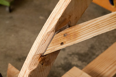
Chine-to-forward-frame connection.

Chine-to-forward-frame connection.

Chine-to-frame-1 connection.


Chine-to-transom connection.
 
Chine-to-stem connection after sanding & initial fairing.


Chine-to-transom connection after sanding & initial fairing.

Monday, May 6, 2013

The Utility, part 3: Stem and floor battens

The Utility’s stem, as with the Squirt, Zip, and I assume several other Glen-L designs, is made of 2 laminations of 3/4” plywood. Fortunately, I had enough 3/4” marine-grade Douglas Fir plywood left over from Lusitania 13’s second transom to build both the transom and the stem for the Utility. 

The laminations are glued together with marine epoxy, (I used Poxy-Shield thickened with #2 silica), and bronze screws. The breasthook is basically made the same way, although the mating pieces are shaped differently: The top piece fits over the stem, and the bottom supporting piece fits around the stem. The breasthook is then epoxied onto the stem. I clearly marked all my centerlines, and tried to make the pieces fit as precisely as possible.

With the centerline on the keel clearly marked, I clamped the Utility’s stem/breasthook assembly into position. Next, using twine and a plumb bob, I worked carefully to make sure the whole assembly was aligned with the centerline of the keel. As a one-person job, this is rather tricky. If you have someone to help, it should be much easier.

With the assembly clamped into position, I drilled two 1/4” holes vertically through the forward part of the keel and aft section of the stem, countersinking the carriage bolts. After applying copious amounts of thickened epoxy, I bolted the stem to the keel with 5” long, 1/4” bronze carriage bolts. After tightening them, I filled the extra space from the countersunk carriage bolts with thickened epoxy.


Stem clamped and bolted onto forward end of keel.

Stem-to-keel joint after epoxy. Glue blocks added for reinforcement.

Having now learned my lesson from having to build up the keel thickness, I turned to the floor battens. As I mentioned before, the frame notches for these were cut to 1” deep. “1-inch” lumber off-the-shelf is typically only 3/4” thick. So, for the floor battens, I purchased an 8-foot, “5/4” mahogany board. (After they plane 1/4” off it at the lumber yard, you’re left with an actual 1-inch thick board.) The cuts for the floor battens were straight cuts, producing four 2” wide battens. Cutting the battens produces a lot, I mean a lot, of red sawdust. I decided to sweep up & collect most of it to use as wood flour to thicken epoxy later on. This turned out to work quite well.


The floor battens had to be fitted into the transom frame notches the same as the keel. The battens were fastened on with thickened epoxy and 2” bronze screws.

Transom knees attached to keel & transom. I put these on before adding the floor battens.


A note about bronze screws

Bronze screw heads are rather soft, and will strip out on you easily. This is particularly true when using a power drill as a screwdriver. Below is the method I used to remove a stripped screw during the fitting process for the floor battens:


Totally stripped-out bronze screw head.

I cut a slot in it with my Dremel.

Removal was then easy with a flat-head screwdriver.

Thursday, May 2, 2013

The Utility, part 2: The Keel

The Utility's keel is made from a 1" x 3" x 8' board, laminated on the inner surface with an additional 1/4" x 3" x 8' plywood backing piece. Optionally, the builder can substitute a 1-1/4" thick solid board. I chose the standard laminating method.

This is where I ran into a little trouble. 

Firstly, I had cut the frame notches as precisely as possible, as-drawn on the plans. For the keel notch, it was 1-1/4" deep. 

Secondly, the "1-inch" mahogany board I'd bought for the keel was in fact only 3/4" thick. (I touched on this in my last post.) So, after laminating on the 1/4" plywood keel backing, the keel was at this point only 1" thick overall.

I briefly considered scrapping the keel and buying a full 1-inch mahogany board to re-build it. The problem there is that mahogany is quite expensive. Also, as you'll read in other boatbuilding blogs (and certainly this one), problems arise. It's a given. If you re-start every time a problem arises, it will take you forever to get the boat built. What I've found is that boat construction, particularly for the first-time builder, involves a lot of troubleshooting. Frankly, that's part of the fun. At least, I think so.

I decided to simply add a second lamination of plywood in order to make up the needed thickness to match the 1-1/4" notch. I did still have some left-over 1/4" marine plywood, but not enough to cut a full 8' length. So, I decided to try my hand at a scarf joint.

Instructions for making scarf joints were included in the plans. Basically, to scarf two sections of 1/4" material, you bevel the ends of each piece along a 3" span. Then, you flip one piece over, fit one diagonal bevel over the other, and glue the two together with epoxy. Creating the bevel is probably best done with a plane, but I didn't have one at the time. So, I used a small Black and Decker sander.


Scarf joint before being glued.
Scarf joint after gluing.

I glued the scarf joint together and added the second keel backing with Poxy-Shield thickened with #2 Silica. The end result wasn't exactly pretty, but it was functional and felt very solid along the full length of the keel.

As with the Squirt, the Utility's transom is raked backward at a 12 degree angle. Notches in the transom frame members must be cut before fastening all the transom parts together. This is because the keel and floor battens do not pass through the transom. Instead, they butt up against the transom. Ideally, the transom frame notches should be cut in such a way so as to match the fitted angle of the transom.

I did not do this. Instead, I simply made perpendicular cuts into the transom frame members. As a result, when the assembled transom was fitted to the construction form, my notches turned "downward" 12 degrees. This meant that for proper fitting, I would need to bevel the ends of the keel and floor battens. I did this using a circular mitre saw cutting on a bias, in addition to using a rasp, file and sander.

In the end, it worked out fine. However, I'd recommend cutting the frame notches at an angle if possible. I believe the final joint would be stronger.


Aft end of keel after beveling.


Beveled keel fit into its transom frame notch.