Friday, October 21, 2016

Cutting beveled notches in the transom

I made a little guide with a 10° bevel on one side, and a 12° bevel on the other. I clamped it into place and used it to help me cut the beveled notches for the sheers, chine, and keel with my multi-tool.


After a little goof from over cutting the first notch, I started clamping a fence into place for the 90° cuts.

The 12° cut is for the keel.
I cut the transom from back-to-front, since the aft-most dimensions are what is marked on the plans. So far, I have not cut any notches for the floor battens. That is because I haven't yet decided if I want to use 3 battens per side, or only 2 (as specified in the plans). I also haven't yet decided — if I do opt for 2 battens per side — whether to use 2" wide battens (as specified), or 2-1/2" wide.

Decisions, decisions...

Monday, October 17, 2016

More transom sanding. More coffee.

So, WHY do I keep sanding this thing at 5:00 in the morning? Partly, because the mahogany wood dust is worth its weight in gold as a thickening agent for epoxy.

That, and I also just need the coffee.

The curved side pieces on the transom frame are, (or rather, were), a bit thicker than the rest of the frame. It would've been fine to leave them that way. However, I decided to sand them down flush with the rest of the frame, and collect the wood dust in the process. It will certainly be needed as I assemble more Zip parts.

Why a sanding block instead of a power sander? Because the power sander blows this wood dust everywhere.


Sweep it up with a brush...

Scoop it up with a squeegee...

...and collect it for future use.

Almost there.

Saturday, October 15, 2016

Of Transom Sanding and Morning Coffee

A single parent's life can get pretty busy. Still, I've been able to work on the Zip's transom a little bit every day. Somewhere in that quiet morning time slot between 4:45 – 5:30, I'd be clutching my morning coffee in one hand, and sanding block in the other.


I've been trimming the top edge of the transom. I used a power sander to remove most of the overhanging plywood, then hand-sanded the rest for a cleaner finish.

In the process of all this, I found that the top of the motor board was not perpendicular to the center line. So, part of the sanding work was to correct that. I also developed a "U-shaped" dip in the motor board, and I had to flatten that out. 


I've basically got the top edge where I want it now. Next will be to cut the beveled notches for the keel, sheers, etc.


Checking the top of the motor board to make sure it's perpendicular to the center line.

Making sure I'd gotten the U-shaped dip out of the motor board. Not perfect, but very close.

Trimmed edge along the port-side top.

Trimming these curves in the transom cutout was a pain.

Sunday, October 2, 2016

Completing the transom frame on the Zip

The last time we discussed the Zip transom in an earlier post, we left off at the need to measure and draw frame lines on the back of the transom. 

The reason for that is fairly simple. The Glen-L plans show the transom drawn to its minimum, aft-most dimension. Not only is the transom mounted at a 12 degree rake, the sides of the boat also flare outward 10 degrees from the transom. So, the front of the transom is actually larger than the back. 

But wait, there's more! 

These beveled angles also mean that the notches for the keel, battens, chines and sheers should be cut at the correct angles for the best possible fit & strongest possible joint. It seems to me that the easiest & most accurate way to make those cuts would be to cut them from the back (as they are drawn on the plans) forward. Thus the need for accurately measured & drawn frame lines on the back of the transom. 

SO, with the back of my transom marked, I was ready to attach the frame parts. 

First, I did the motor board. I used epoxy, thickened with mahogany wood dust, to simply glue it into place. I did not use screws or nails. Clamping it into position accurately was a bit of a challenge, but I got it. Learning from past experience, I meticulously scraped away the epoxy squeeze-out. If left to cure in corners, etc, dried epoxy will create a fitting nightmare. 


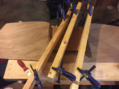
Attaching the motor board, using multiple clamped 2x4s to press the motor board firmly into place.
Next came the floor beam, a few days later. Thanks to the well-scraped joint between the motor board and the plywood, fitting the floor beam was a cinch. I used the same epoxy-only method as with the motor board. I had over-estimated how much epoxy to mix. I had enough left over to go ahead and attach the side frame members as well. 


Attaching the floor beam and frame sides.
To the naked eye, the curved sides of the Zip transom may look like a symmetrically-cut oval, but they're not. The top is slightly narrower than the bottom. That is why I had marked the starboard and port sides with corresponding "up" arrows. This let me know, at a glance, which side to put the epoxy on, and which way to orient the piece on the transom.


Transom frame sides, marked for Starboard and Port
A couple of weekends after G10, I attached the top frame members, again using the same epoxy-only technique. It's a good, sturdy and solid transom that will only get stronger as I add another 1/2" thickness to it in the future. 


Glen-L Zip transom
Beginning to trim the edges on my Zip transom.

For now, the next step is to trim the edges, and cut the notches for the keel, chine and sheer.