Saturday, June 25, 2016

Battery mount installed & a few other things

Let's just get right to the pictures:

I did the touch up painting on the stem, adding two coats of Whidbey White to the battery mount supports...


Here is the actual battery mount, with the Attwood battery box mounting hardware reattached. As planned, I coated the underside of it with 1 layer of thickened epoxy, which I also applied to the top of the supports. I pressed them together, and now it's just a matter of waiting for the epoxy to cure.


Battery mount, epoxied into place.

I arranged my plan for clamping the switch panel underneath the starboard quarter knee. Finally, I was able to justify buying those Bessey variable spring clamps I bought a long time ago...


I marked and drilled the holes for mounting the bilge pump switch to the panel. Here it is, mocked-up in position, before I removed the switch and epoxied the panel into place.


Switch panel, epoxied into place.


I decided how I would mount the removable panel that will hold the bilge pump into position. I'll attach the base of the bilge pump to a 1/4" plywood base. I'll secure the base to the side of the transom knee. Since the flat surface of the plywood will not allow for any rotation, I believe I can safely secure this into place with only one screw or bolt.


Bilge pump panel, assembled & coated with first layer of epoxy.

And lastly, in other news... I added another pair of fender cleats at the back of the gunwale. The last time I had the boat out, I quickly got tired of having to use the rear cleats for both docking lines AND fender lines.


Friday, June 24, 2016

Incremental progress on the battery mount

The last week has been dominated by the tragic and unfortunate death of my ex-wife. Now, I'm back to work on Perseverance... though I haven't got much done.

I'm continuing to work on the battery mount. No major progress to report, but I've gotten the miscellaneous mahogany parts encapsulated with two coats of epoxy. 

The exception is the underside of the battery mount itself. I want to be able to epoxy bare wood surfaces together, when I attach the battery mount to the support brackets. For encapsulation, I will probably just coat the entire underside of the battery mount with one layer of thickened epoxy and attach it to the support brackets all at the same time.


After adding a second coat of epoxy to the support brackets, I used mahogany sawdust left over from sanding the Zip's motor board to thicken the remaining epoxy in the batch. I used that to glue the brackets to the stem.

Next step for the brackets is to paint them Whidbey White, along with touch-up paint on the stem.
I used DAP Plastic Wood to fill the holes on the end blocks of the battery mount.  Here, it is simply resting in position.
Also encapsulated with a second coat of epoxy is this small panel for the bilge pump switch.

I'm planning to install the bilge pump switch underneath the rear starboard quarter knee.


And finally, a couple of photos from better days... in a time and place far, far away. These were taken in northern Italy in 1998. RIP.


1977 – 2016
1977 – 2016

Sunday, June 12, 2016

Building the battery mount

I've had Perseverance out on the water three times now. Something I've learned, not surprisingly, is that performance is improved somewhat by shifting a certain amount of weight forward.


Glen-L Utility
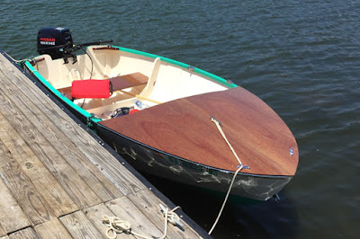
Perseverance at the dock, yesterday afternoon

Part of that has to do with the fact that the boat is driven from the aft seat. Another part of the equation is the admittedly limited power of its 8hp motor. With just me aboard, the 8hp Nissan does a fine job. However, with another adult-sized person in the boat, the motor struggles somewhat.

There is also a necessary balance. As I found out with my son in the boat yesterday, shifting too much weight too far forward makes the boat want to plow at full throttle.

So, back to the point: I wanted to mount the battery forward, to help with planing performance.... or at the very least, to keep from putting more weight unnecessarily in the back.


Sanding the excessive epoxy runs off the side of the stem.
Fitting the battery mount supports.


After a little more sanding on the stem, and filing the notches in the mahogany supports, they finally fit.


The mount itself is also made from mahogany, and will be epoxied to the supports.

My original plan was to bright-finish the whole battery mount, but since the supports are not visible from any angle, I will probably just paint them Whidbey White, along with touch-up paint on the stem.
I'm using an Attwood small battery box, along with the included mounting hardware that fits into grooves underneath the box.

I'll also place mahogany blocks on either side, to prevent side-to-side movement. Theoretically, the included hardware should limit front-to-back movement. We'll see.

Thursday, June 2, 2016

90% done... 90% left to go.

As I near the completion of the Utility project, my remaining "to-do" list seems to be getting longer... not shorter.

Part of that is due to the bilge pump I've yet to install. The pump itself must be mounted to the hull. There's the switch that needs to be wired. The switch must be mounted, which means I need to build a place to mount it. The pump, of course, requires a battery (which fortunately I do have). Still, I have to build a mount for the battery. I have actually been working on that the last few days, but no photos just yet. That'll have to wait for another post.

In the meantime, I can celebrate one more layer of varnish on the deck... and complain a little about the trailer lights.


The Varnish


Sanding the third coat of varnish

More sanding...

More sanding...

4th coat of varnish!

The Trailer Saga Continues

In the last post, I mentioned that I was unable to install the new bow roller. That is because the center hole was too small for the existing pin that holds it to the bracket. I had assumed I could simply buy a new pin. That turned out to be less easy than I wanted it to be.

Did I mention that I have an OLD trailer? According to the manufacturer's records, the trailer is as old as I am... a 1970 model. It's a darn well-made trailer. And apparently, that was back in the day when a 5/8" diameter pin was manufactured to 5/8" diameter.

The new bow roller was "labeled" as 5/8".... and apparently made for a new-fangled 5/8" pin that is manufactured to something less than 5/8" diameter. I can only assume, because in spite of the plethora of rollers to be purchased, there was not one pin to be found. At least, not before I finally realized that a smaller diameter pin would also mean I'd have to replace or modify the mounting bracket as well.

That's when I remembered that I have a perfectly functional drill press.

So, I bored out the hole, and the old pin fit just fine. 

The next problem was the fact that the new bow roller was more narrow than the old mounting bracket. No problem. An old hole saw from a doorknob mounting kit, a piece of leftover vertical-grain pine... and next thing you know, I had a couple of wooden washers / spacers that work just fine.


The Trailer Lights

Now... on to complaining about the trailer lights.

In the last post, I had facetiously remarked about my daughter's superb tape job on the side marker light that had fallen off on it's maiden voyage.


When I started pulling the tape off... (and pulling... and pulling... and pulling...) I realized just how much tape she had used.


In short order, I came to regard her tape job as a notable structural upgrade from the originally-supplied mounting hardware.

The lighting kit I had purchased is an Optronics submersible trailer light kit from Cabela's. Truthfully, it was an easy-to-install kit that I'm happy with overall. The side marker lights, however, only have one mounting bolt each... not two. That means the lights can be more prone to rotating. Maybe not a major issue... but two bolts would have been preferable.

The mounting hardware included a small lock washer and nut, made from some pretty cheap-looking material. I decided to re-attach each light with stainless steel lock nuts and fender washers, since the original washers were a bit small in relation to the mounting hole in the trailer.

Fender washer and lock nut

However, shortly after I began threading on the first lock nut, the entire bolt began to rotate inside the light assembly. The original had used a lock washer, because the bolt is not fixed into place inside the light assembly. The lock nut requires more torque.... too much for the bolt to stay in place.

So, I removed the amber lens to see what I could do.


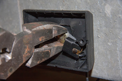
I could see the rotating bolt head. However, I couldn't grip it with pliers without risking breaking the light bulb. 

Fortunately, the bulb could simply be pulled free from its mounting clip. 


Then, I could grip the bolt head with a pair of pliers and hold it in place while I finished tightening the lock nut. 


With the light assembly firmly in place, I plugged the bulbs back in and re-attached the amber lenses... and hoped nothing went wrong in the process.

So, I plugged the trailer lights back up to the car...


...and thankfully, everything worked just fine.